/

/

Search
Category
2026-11-06
Industry News
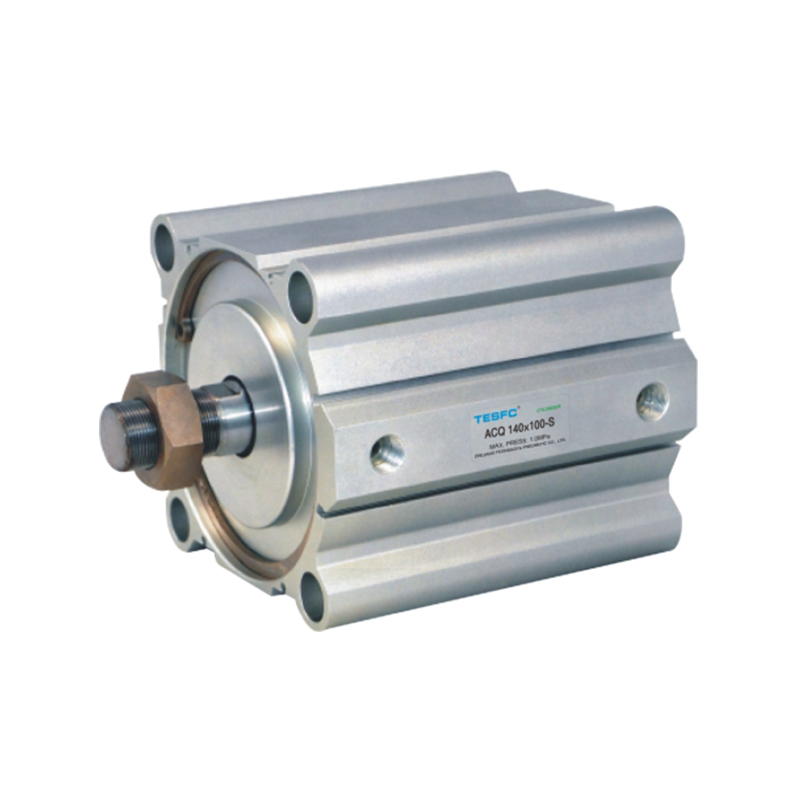
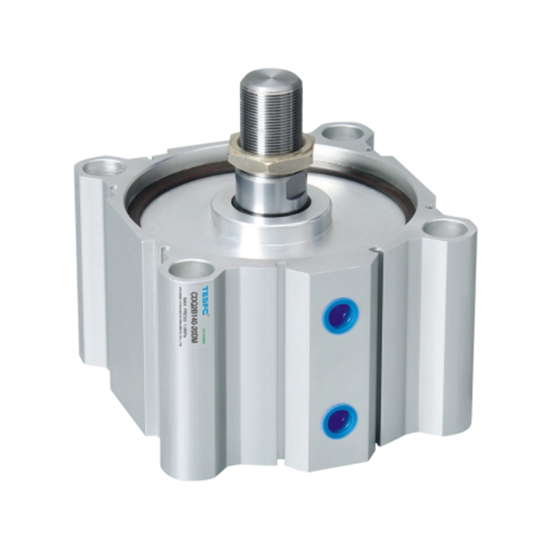
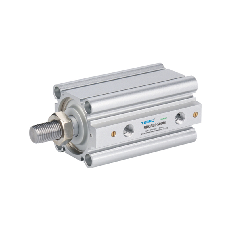
A pneumatic cylinder that arrives after brackets are welded and valves are plumbed can stop an assembly line as effectively as a missing part. Mounting holes that do not line up, a stroke that falls short of the mechanism's travel, or a port thread that rejects the chosen fitting force redesign work at the worst moment. Compatibility is therefore confirmed while the design is still on paper and the cylinder is still in its box. Small Bore Air Cylinders used in compact automation are especially sensitive to these checks because clearances are tight and later modification is expensive.
Series, bore, stroke and any option codes are read from the nameplate or packaging and compared with the bill of materials and the assembly drawing. Accessories that were assumed to be included—clevises, mounting brackets, sensor rails—are confirmed as present or listed as separate items. A partial model match is treated as a discrepancy until resolved.
The official datasheet and outline drawing for the precise configuration are obtained. Operating pressure range, port details, allowable environments and mounting options are taken from that document alone. Literature for a similar but not identical variant is set aside.
Cylinder data are laid against the pneumatic schematic and the mechanical layout. Differences in stroke, mounting pattern or port orientation are noted and closed before the cylinder is offered to the fitter. Unresolved differences become assembly problems later.
Overall length, width and profile are checked against the space reserved on the machine. Adjacent brackets, covers, cable ducts and other actuators are included in the check so that the cylinder does not share volume that was counted twice in the design.
The mounting style shown on the drawing—foot, flange, trunnion, through-hole or another arrangement—is compared with the holes or surfaces provided on the machine. Fastener sizes and edge distances are verified. The supporting structure is confirmed as able to take the mounting loads without local distortion.
Length with the rod fully in and fully out is calculated or taken from the drawing. The path of the rod end and of any attached linkage is swept mentally or with a simple mock-up to find clashes with frames, guides, sensors or workpieces. Interference discovered at this stage is cheaper to fix than interference discovered under power.
Catalogue phrases that describe mounting flexibility are read against the actual holes, threads and recommended brackets in the product drawing. Extra supports or alignment pieces are added to the design when the application needs them rather than assumed to be optional.
The distance the machine must move—including any over-travel for switches or mechanical stops—is measured from the design. That distance is compared with the cylinder's nominal stroke. Connecting links and fixture thickness are included so that the rod does not run out of travel before the mechanism reaches its end position.
The load to be moved, friction in guides, direction of motion and any process forces are estimated. Available thrust or pull at the intended supply pressure is taken from the datasheet and compared with that demand. A margin consistent with the application and with engineering practice is left; pressure is not raised beyond the cylinder's rated range to compensate for an undersized bore.
Line pressure at the machine is confirmed to lie inside the cylinder's allowable band. Regulators, valves, tube bore and fittings are checked for the flow the cycle requires. A supply that is adequate for a slow test may starve a fast production cycle.
Forces that push across the rod axis are identified. Alignment between cylinder, coupling and guided load is verified. Where the mechanism cannot keep the load on the rod centreline, an external guide is specified. The rod is not used as the sole linear guide when the application generates significant side load.
Port threads are read from the datasheet and matched to the fittings in the parts list. Visual similarity of threads is not accepted as proof of compatibility. Fitting bodies are checked for clash with nearby structure once installed.
Routes are planned so that tubes neither stretch nor pinch through the full stroke. Bend radii and lengths leave enough slack for motion without rubbing on edges or on other moving parts.
The directional valve's configuration, porting and flow capacity are confirmed against the cylinder's needs and the intended cycle speed. Control logic that expects a double-acting cylinder is not paired with a single-acting body without a design change.
Whether the control system must know that the cylinder is extended, retracted or both is decided from the sequence diagram. Sensor compatibility and mounting provisions are taken from the cylinder documentation. Brackets or grooves required for the chosen sensor are confirmed as present or ordered.
Supply voltage, output type and wiring of the sensor are matched to the controller inputs. The way the signal is used in the sequence—interlock, step enable or fault detect—is defined so that missing or inverted logic is caught before commissioning.
Extension and retraction commands are checked against the timing of other actuators and guards. Simultaneous motions that would collide are separated in the sequence or in the mechanical layout.
Temperature, humidity, dust and any corrosive or wet conditions are compared with the limits stated for the cylinder. Additional protection or a different product variant is considered when the application sits outside those limits.
Cycles per minute and expected life in the application are set beside the manufacturer's guidance. Not every compact cylinder is intended for continuous high-frequency duty; the datasheet remains the reference.
Fittings, mounting screws and sensor clamps must remain reachable for inspection and replacement. Tube connections and adjustment points are left clear of permanent covers where possible.
Model number and critical dimensions are checked once more against the approved drawing. Mounting faces, rod end and surrounding clearances are inspected. Differences are recorded before assembly continues.
The cylinder is offered up to its mounts without full tightening. Rod travel, fitting clearance and tool access are confirmed. The driven mechanism is moved through its range by hand where safe to do so.
Commissioning follows the manufacturer's instructions. Air is applied within the specified pressure band with people clear of the motion path. Extension, retraction, leakage and any binding or noise are observed. Faults are corrected before the cylinder is tied into the full automatic sequence.
Model, key specifications, inspection notes, trial-fit results and any approved deviation are written down. The record supports later fault finding and spare-part decisions.
Wrong drawing revisions or similar model numbers cause to holes that do not align. The exact model and its official drawing are verified before any machine bracket is altered.
Insufficient travel leaves the mechanism short of its stop. The full motion, including linkages, is checked before the stroke is accepted.
Bore and pressure together define available force. When the load exceeds that force, the application is recalculated; pressure is not pushed past the rated limit.
Connections and cables routed after the cylinder is fixed often foul the stroke or block maintenance. Clearances for accessories are included in the trial fit.
A cylinder that bolts in place may still fail to operate correctly if the valve, sensor or sequence logic does not match. Pneumatic and electrical compatibility are verified with the same care as the mounting holes.
Complete model and options are confirmed. Bore, stroke, envelope and mounting pattern are compared with the drawing. Required force is checked at working pressure. Ports, fittings, tubes and valve are matched. Sensors and control use are verified where needed. Environment, duty and access are reviewed. Trial fit and a basic functional test are completed and recorded before the machine is closed.
A compact free-mounting cylinder is a candidate only when its documented dimensions, mounting arrangement and operating data match the machine design. Official drawings and technical data are reviewed before the model is released for assembly.
| Check | Purpose | When to Complete |
|---|---|---|
| Model and datasheet | Ensure correct configuration and limits | On receipt, before any fitting |
| Envelope and mounting pattern | Prevent clashes and hole mismatches | Against layout drawing and at trial fit |
| Stroke and force | Meet travel and load demand | During design review and after pressure is known |
| Ports, tubes, valve | Secure supply and exhaust without interference | Before hard tubing is cut |
| Sensors and sequence | Align feedback with control logic | With electrical design and during dry-cycle tests |
| Environment and access | Keep product within ratings; allow future service | Layout stage and final assembly review |
| Trial fit and safe air test | Catch residual errors before full integration | Immediately before permanent installation |
Dimensional match, pneumatic capacity and control interface must all be proven before a cylinder is committed to the machine. A documented trial fit and a careful functional test close the loop. Zhejiang Feishengya Pneumatic Components Co., Ltd. manufactures small bore pneumatic cylinders for automation equipment. Review of model designation, dimensional drawings, force data and connection details against the machine design supports selection and installation of a cylinder that fits the assembly without late mechanical or control changes.
RECOMMENDED PRODUCTS

Phone: +86-15957736756
E-mail: [email protected]
Add: No.7, Yongxing Second Road, Chengdong Industrial Functional Zone, Chengdong Subdistrict, Yueqing City, Zhejiang Province, P.R.China
Copyright © Zhejiang Feishengya Pneumatic Components Co., Ltd. All Rights Reserved.
 Pneumatic Component Factory
 English
 русский
 عربى
 Español